

Limit smoke spread and maintain tenable escape/firefighting conditions
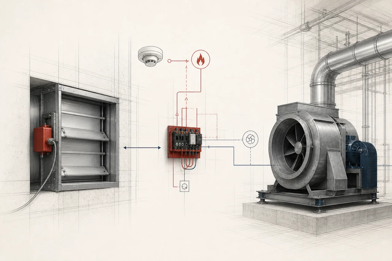
Smoke management
Smoke control and damper interfaces
Smoke control helps keep escape and firefighting access usable by managing where smoke moves. Your system may use fans, dampers, vents, barriers or pressure differences. Its connection to the fire alarm needs to carry out the approved smoke-control sequence and report whether equipment has responded.
System snapshot
Key system characteristics
The same fields are used across every solution guide, making the systems easier to compare without reducing the decision to a single product.
Automatic fire logic with firefighter manual override
None, but incorrect operation can worsen smoke movement
Very high - leakage, doors, shafts and wind affect performance
Power, fan run/trip, damper position, pressure and communication
Stuck dampers, changed controls, worn actuators, blocked paths and altered partitions
How the system works
Smoke control helps keep escape and firefighting access usable by managing where smoke moves. Your system may use fans, dampers, vents, barriers or pressure differences. Its connection to the fire alarm needs to carry out the approved smoke-control sequence and report whether equipment has responded.
Key selection considerations
- 01
Performance feedback: A relay command without end-position or performance feedback may not prove the damper or fan achieved its fire state.
- 02
Pressure control: Door opening forces, leakage and wind can undermine pressure-differential systems.
- 03
Integrated testing: Smoke control is a whole-building mechanical performance problem; fragmented trade testing misses sequence failures.
- 04
Building changes: Changes to partitions, doors, fan controls or tenant systems can invalidate commissioned performance.
System anatomy
System components and approvals
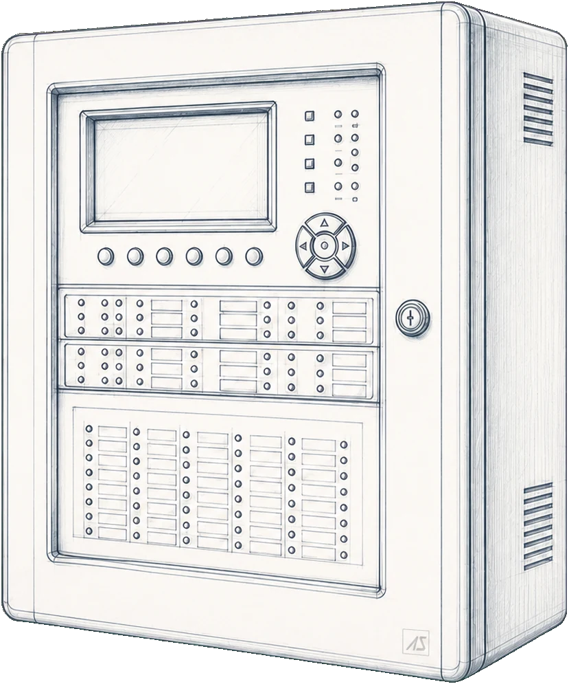
Smoke-control panel or fire alarm interfaces
Use approved control/I/O equipment with monitored circuits and defined overrides.
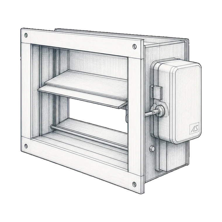
Smoke and fire dampers with actuators
Dampers and actuators require the applicable fire/smoke performance and installation system.
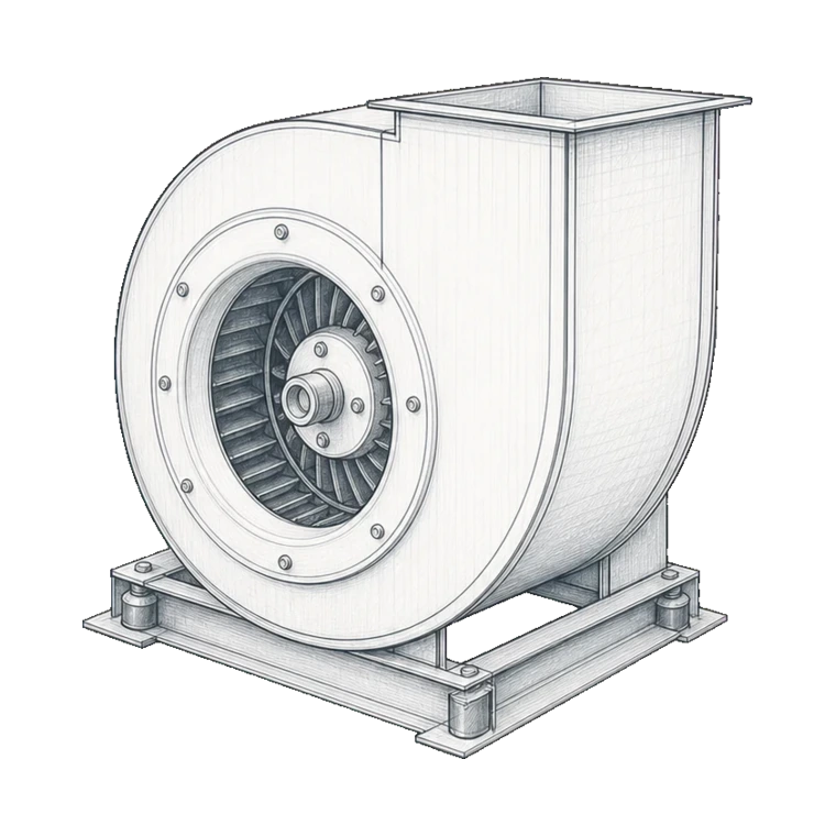
Fans, drives and starters
Temperature rating, duty, power and control arrangement follow the smoke strategy.
Ducts, shafts, vents and barriers
Construction and leakage/fire resistance need applicable tested evidence.
Pressure and position sensors
Feedback points must prove the performance states required by the strategy.
Firefighter override controls
Priority, indication and safe manual operation require authority agreement.
Approval families
Typical approvals and certification requirements
- ISO 21927 / EN 12101 smoke and heat control component and system standards
- NFPA 92 or locally adopted smoke-control design rules
- Approved fire/smoke dampers, actuators, fans, ducts and control equipment
- Integrated systems testing requirements such as NFPA 4 where adopted
Governing rules
Codes, standards and project rules
- 01
The approved fire engineering/smoke-control report defines zones, scenarios and required states.
- 02
ISO 21927 and EN 12101 address specific components and systems; NFPA 92 is a common engineering reference in NFPA jurisdictions.
- 03
Integrated testing should verify the complete sequence under normal, emergency and fault conditions.
Design information
Information needed to design and quote the system
Complete inputs reduce assumptions, expose interface risks early and make competing proposals meaningfully comparable.
- 01
Approved fire strategy, design fires, smoke zones and tenability criteria
- 02
Mechanical drawings, fan curves, ducts, shafts, vents and leakage assumptions
- 03
Damper schedule, actuator type, normal/fire position and feedback
- 04
Cause-and-effect for detectors, fans, doors, lifts and overrides
- 05
Primary/emergency power and cable survivability
- 06
Commissioning scenarios, pressure/flow measurements and integrated witness plan
Inspection, testing and maintenance
Inspection, testing and maintenance requirements
Frequency and method must follow the adopted standard, authority conditions and manufacturer instructions. These recurring activities belong in the maintenance plan.
- 01
Inspect and exercise dampers, actuators, fans, vents, doors, sensors and override controls.
- 02
Verify command and actual feedback, including fail-safe operation after power or communication loss.
- 03
Periodically perform integrated scenario tests and required pressure, airflow or door-force measurements.
- 04
Review modifications across fire alarm, BMS, mechanical and architectural trades before closing change records.
Mapped manufacturers
See all brands
Brands that support this solution
Siemens
Siemens for fire detection and control.
Honeywell
Honeywell for fire detection and control.
Schneider Electric
Schneider Electric for marine, offshore and industrial equipment.

ABB
ABB for marine, offshore and industrial equipment.
Range, approval, territory and project suitability remain model-specific and are confirmed for each enquiry.
Delivery and lifecycle services
Services needed across the system lifecycle
Appointments, licences and authority requirements vary by country. We confirm what the service must include before work starts.
Solution designFire safety drawings, calculations, equipment schedules and approval documents for coordinated projects.
Land installationInstallation, integration, testing and handover of building and industrial fire safety systems.
PLC programming and integrationPLC logic, fire-system interfaces, acceptance testing, backups and controlled change records.
Testing and commissioningDevice, circuit, interface and cause-and-effect testing with traceable commissioning records.
Statutory system testing and maintenanceScheduled inspection, testing, maintenance and defect reporting for installed fire safety systems.
System certification supportProduct, design, installation and test evidence prepared for authority, class or certification review.
TrainingPractical, system-specific training for operators, facilities teams, technicians and emergency responders.
Research basis
Standards and official references
These sources establish the system context. Verify the edition adopted by the project and the current certificate for the exact model.
Related knowledge
Knowledge base
Related technical guides

Guide to smoke detection in commercial buildings
Understand detector types, placement and selection factors.
Read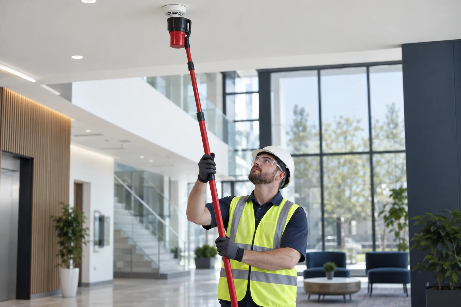
Testing detectors in difficult-to-access locations
Compare access poles, installed test systems and safe maintenance planning.
Read
Writing a fire-alarm cause-and-effect matrix
Organize initiating events, outputs, interfaces, timing, reset and test requirements.
ReadCommon Questions
Frequently Asked Questions
Can the BMS control smoke dampers?
It can participate where the approved strategy permits, but fire-mode priority, fail-safe behavior, supervision, feedback and firefighter override must be clearly defined.
Why is end-position feedback important?
It distinguishes a command from proof that the damper or device actually reached the required state.
When should smoke control be recommissioned?
After relevant architectural, mechanical, fire alarm, BMS, door or power changes and at the periodic interval required by the adopted regime.