

Control, indication, occupant warning and safety-system interfaces
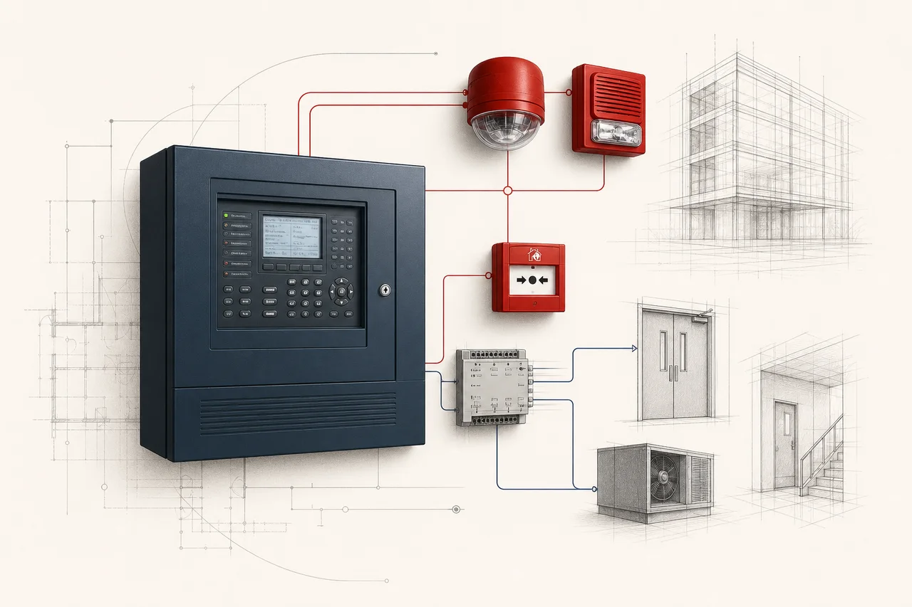
System coordination
Fire Alarm Control & Warning System
Your fire panel connects detection with action. It receives signals, shows alarms and faults, activates warnings and controls connected equipment. The important part is how those functions work together in your building, from each detector input to each programmed response.
System snapshot
Key system characteristics
The same fields are used across every solution guide, making the systems easier to compare without reducing the decision to a single product.
Inputs from detection, manual controls and connected systems
None directly; outputs can initiate shutdown or suppression
Low
Central function: circuits, power, network, earth faults and disabled points
Panel obsolescence, software access, batteries and protocol migration
How the system works
Your fire panel connects detection with action. It receives signals, shows alarms and faults, activates warnings and controls connected equipment. The important part is how those functions work together in your building, from each detector input to each programmed response.
Key selection considerations
- 01
System access: An open detector protocol does not mean unrestricted access to panel programming, graphics or network configuration.
- 02
Cause and effect: Cause-and-effect must distinguish alarm, supervisory, fault, disablement and manual override states.
- 03
Warning coverage: Audibility, speech intelligibility and visual coverage require calculations and field verification; device quantity alone is not proof of coverage.
- 04
Building interfaces: Interfaces to lifts, doors, dampers, fans, gas valves and suppression systems need feedback, fail-safe states and coordinated witnessing.
System anatomy
System components and approvals
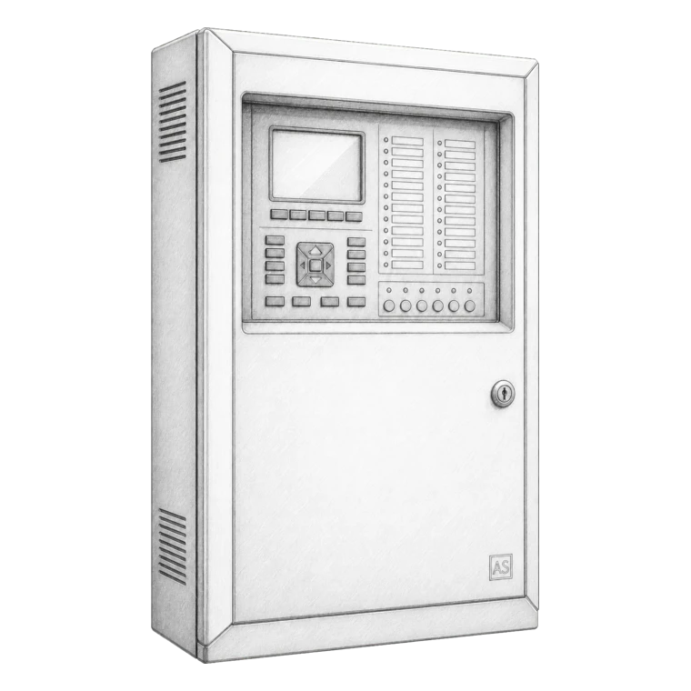
Fire alarm control panel and network nodes
The platform and network arrangement should carry the required system approval.
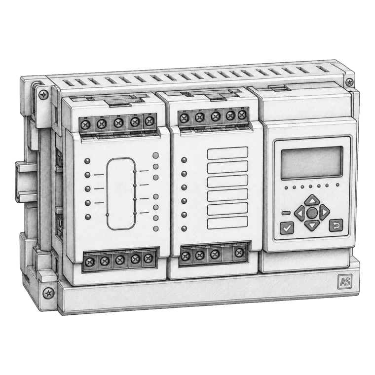
Loop cards, zone cards and repeaters
Verify approved compatibility, firmware and capacity.
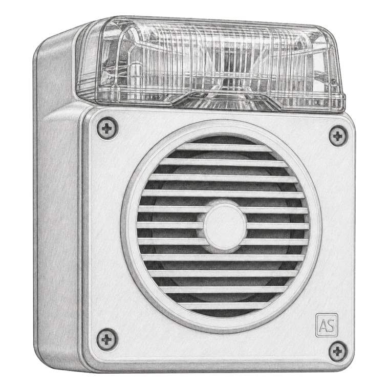
Sounders, speakers, beacons and visual alarm devices
Use approved devices and calculate audible/visual coverage and circuit load.
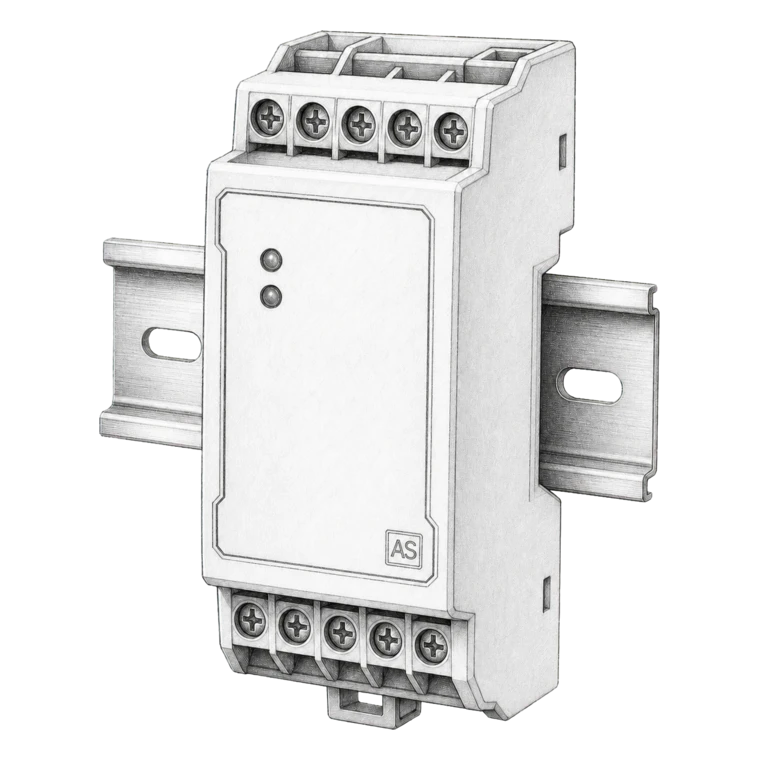
Input/output and relay interfaces
Use supervised, approved interfaces where the fire system relies on the function.
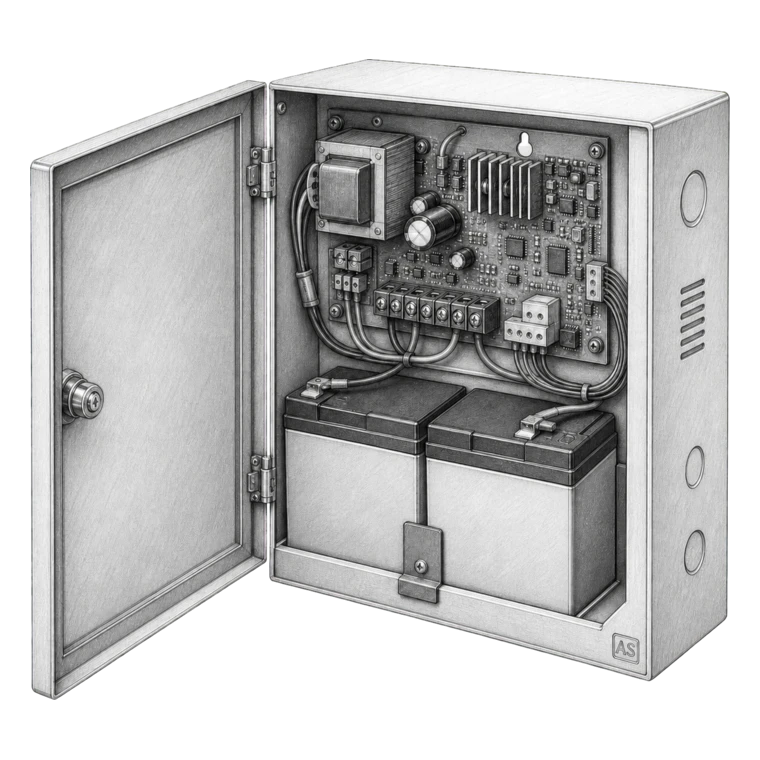
Power supplies and batteries
Approved, fault-monitored and sized for the adopted standby and alarm period.
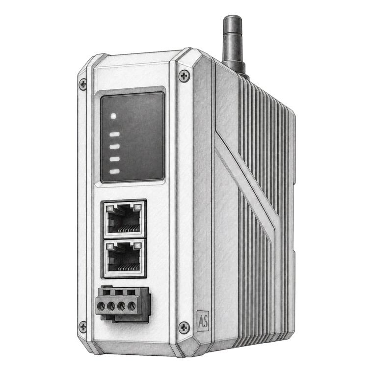
Graphics, gateways and transmission equipment
Confirm approval boundary, cybersecurity, loss-of-communication behavior and monitoring.
Approval families
Typical approvals and certification requirements
- ISO 7240 / EN 54 control, power, alarm-device and interface standards
- UL 864 and compatible listed initiating and notification equipment where required
- LPCB, VdS, FM or regional approval schemes specified by the project
- Marine type approval, MED and class acceptance for vessel systems
Governing rules
Codes, standards and project rules
- 01
NFPA 72, ISO 7240-14 and local fire codes commonly govern documentation, circuit supervision, notification, interfaces and testing.
- 02
Where multiple life-safety systems interact, integrated testing may be governed by a standard such as NFPA 4 or a local integrated systems test requirement.
- 03
Programming changes should be controlled, backed up, documented and regression-tested against the approved cause-and-effect.
Design information
Information needed to design and quote the system
Complete inputs reduce assumptions, expose interface risks early and make competing proposals meaningfully comparable.
- 01
Complete input/output and cause-and-effect matrix
- 02
Loop, zone, network and I/O capacity with expansion allowance
- 03
Audibility, visibility, intelligibility and accessibility criteria
- 04
Interfaces, normal/fail-safe states, feedback and manual overrides
- 05
Standby power calculations and circuit survivability requirements
- 06
Programming access, graphics, event reporting and cybersecurity expectations
Inspection, testing and maintenance
Inspection, testing and maintenance requirements
Frequency and method must follow the adopted standard, authority conditions and manufacturer instructions. These recurring activities belong in the maintenance plan.
- 01
Review panel indications, event logs, batteries, printers, networks, repeaters and all disabled or isolated points.
- 02
Test representative circuits and devices at the frequencies required by the adopted standard, ensuring every device is exercised within the prescribed cycle.
- 03
Witness the complete output sequence, including notification, transmission, shutdown, door, lift, damper, fan and suppression interfaces.
- 04
Back up configuration data after authorised changes and retain version, test and defect records.
Mapped manufacturers
See all brands
Brands that support this solution
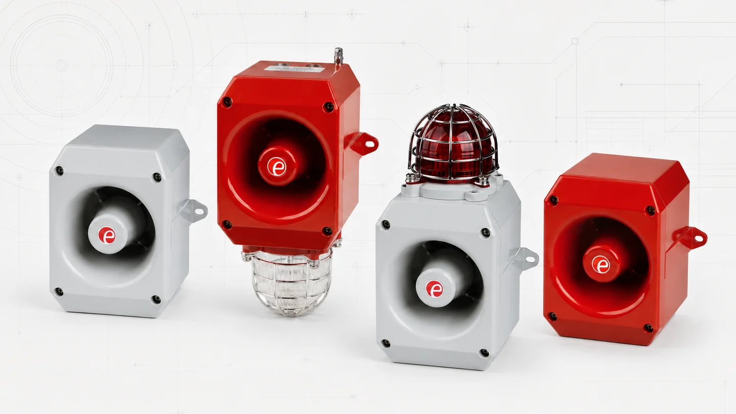

Audible and visual warning selected for the marine environment
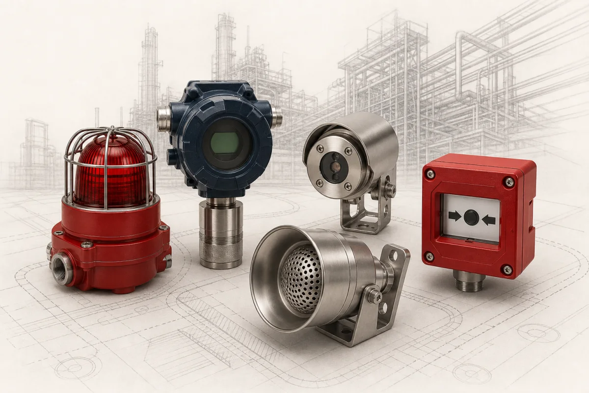

Marine loudspeakers matched to the public address and warning system
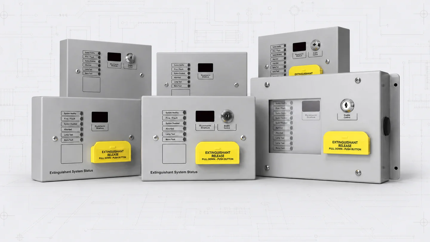

Marine addressable control in the specified Syncro ASM configuration
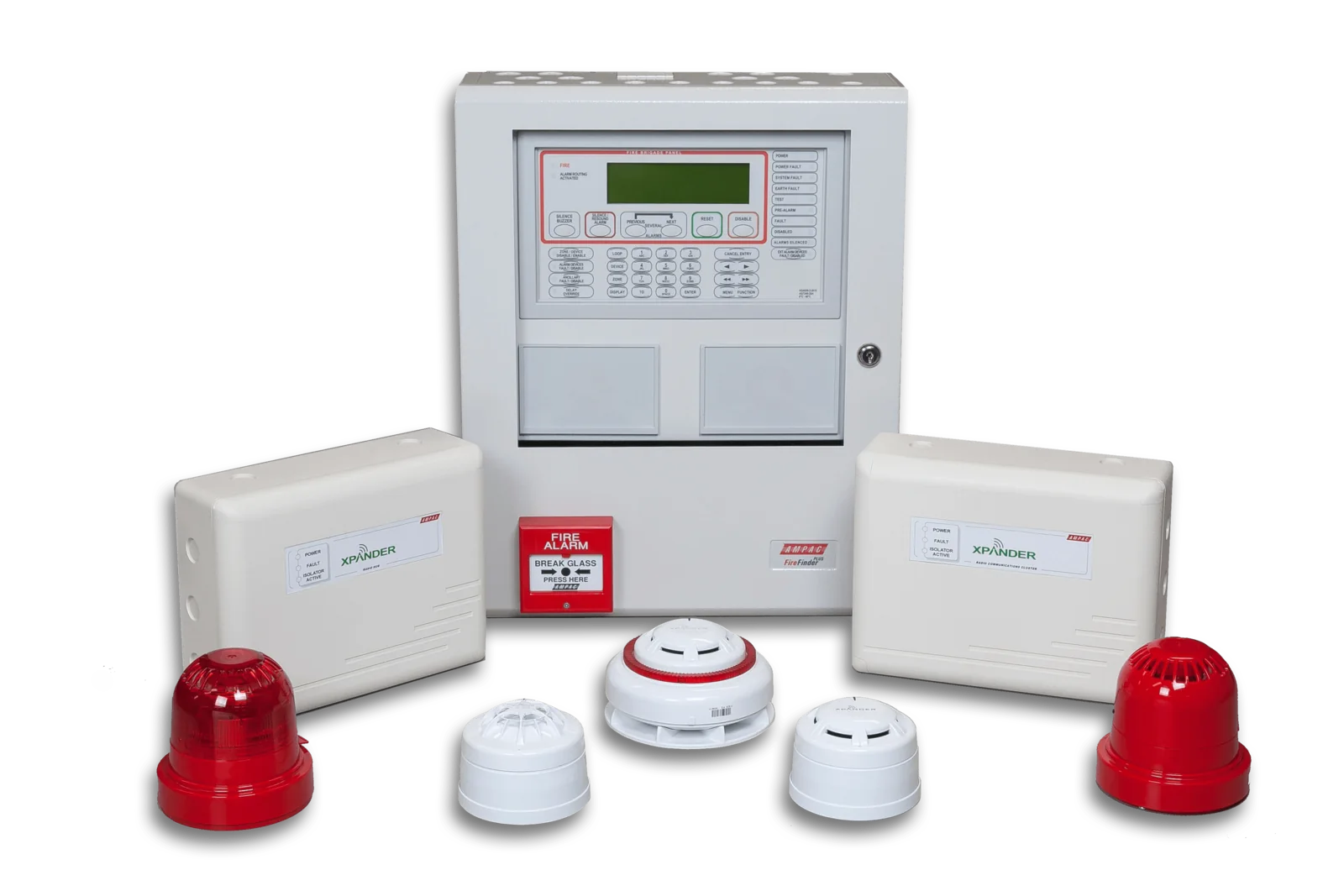
Ampac
Marine fire detection and alarm control in approved configurations
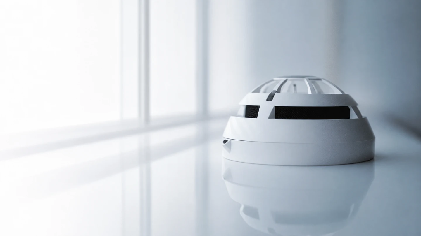

Compatible detection devices selected for the marine panel and approval
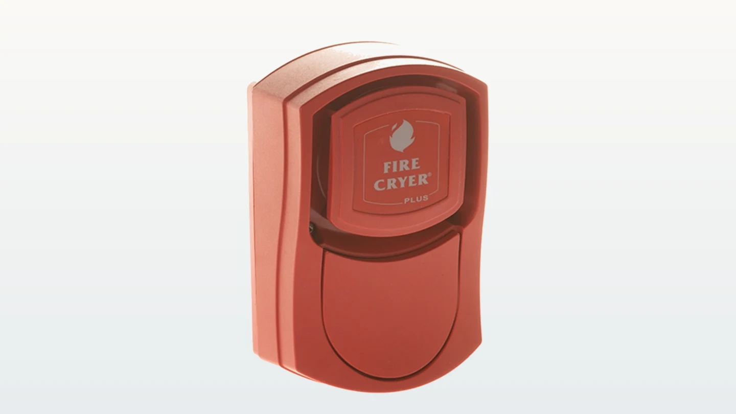

Alarm, evacuation and supporting life-safety equipment.
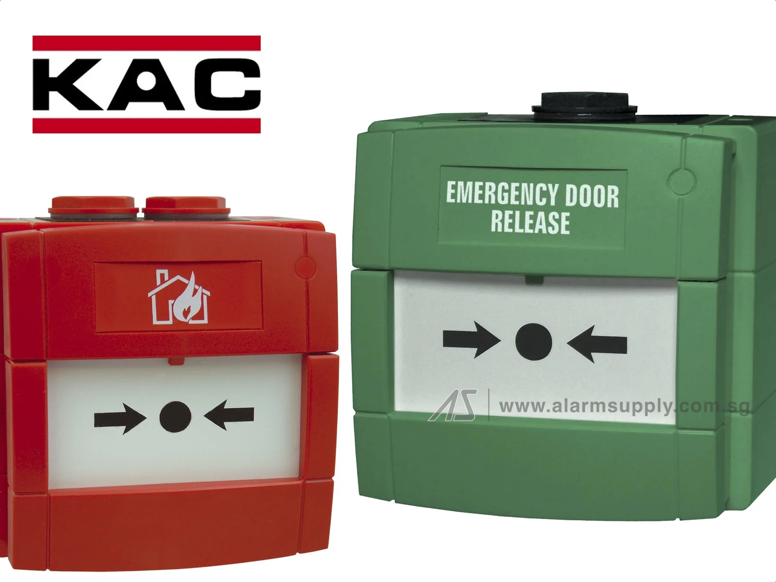

Manual call points and specialist initiating devices.
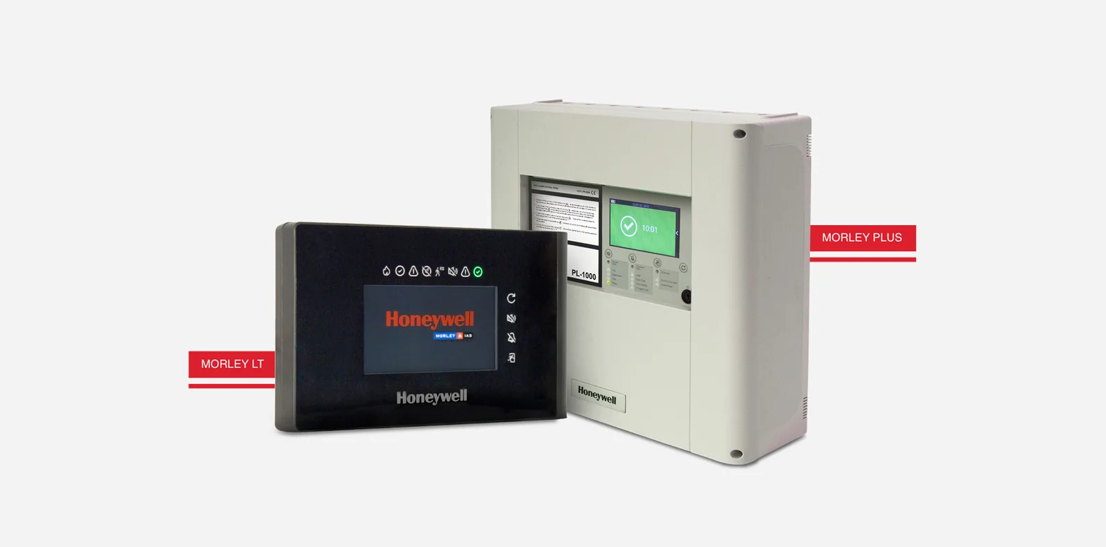
Honeywell
Honeywell for fire detection and control.
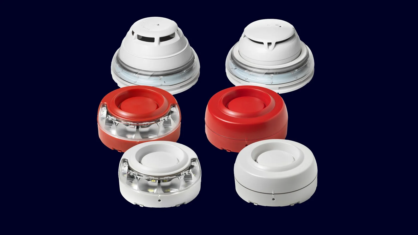
Siemens
Siemens for fire detection and control.
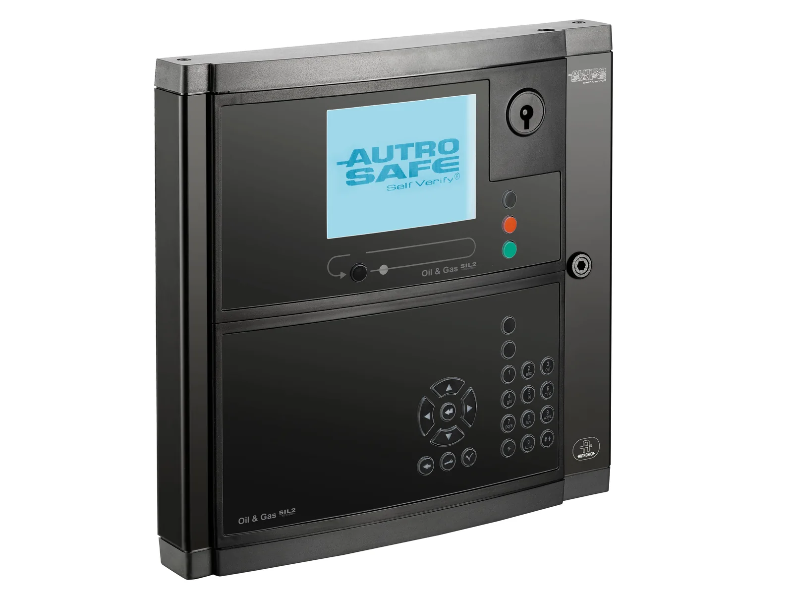
Autronica
Autronica for fire detection and control.
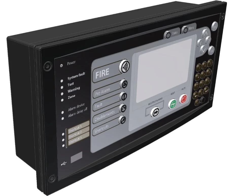
Consilium
Consilium for fire detection and control.
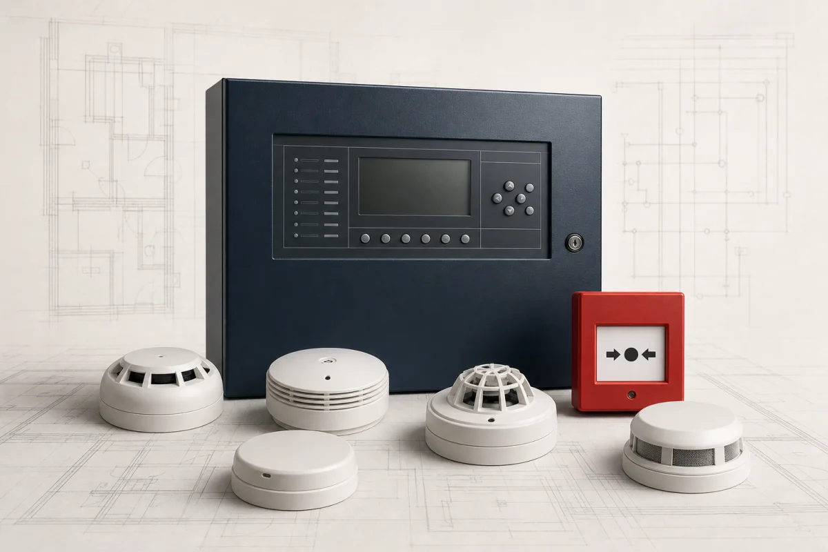
Salwico
Salwico for fire detection and control.
Range, approval, territory and project suitability remain model-specific and are confirmed for each enquiry.
Delivery and lifecycle services
Services needed across the system lifecycle
Appointments, licences and authority requirements vary by country. We confirm what the service must include before work starts.
Solution designFire safety drawings, calculations, equipment schedules and approval documents for coordinated projects.
Marine installationMarine fire-system installation and replacement with flag, class and vessel requirements addressed.
Testing and commissioningDevice, circuit, interface and cause-and-effect testing with traceable commissioning records.
Statutory system testing and maintenanceScheduled inspection, testing, maintenance and defect reporting for installed fire safety systems.
Research basis
Standards and official references
These sources establish the system context. Verify the edition adopted by the project and the current certificate for the exact model.
Related knowledge
Knowledge base
Related technical guides
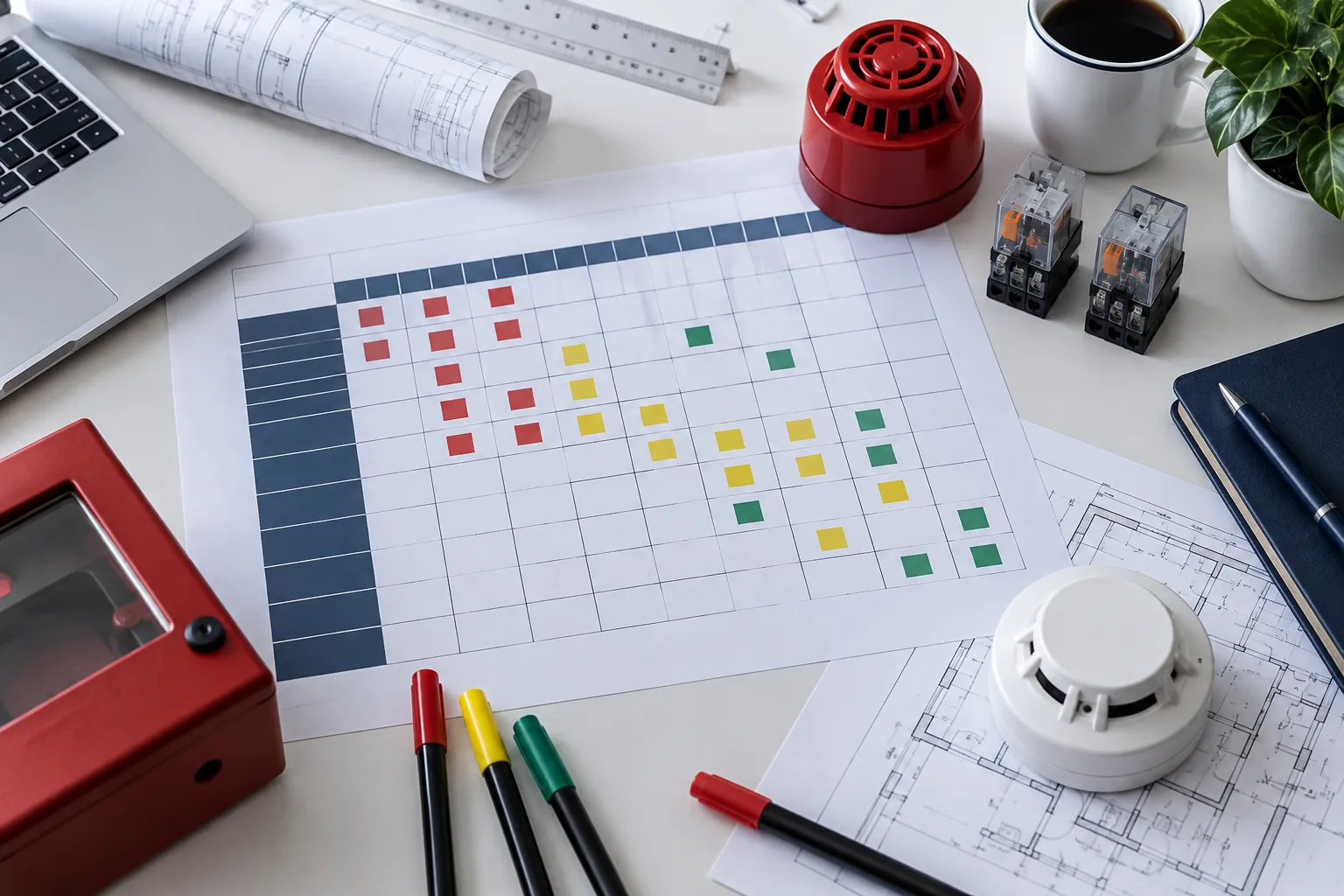
Writing a fire-alarm cause-and-effect matrix
Organize initiating events, outputs, interfaces, timing, reset and test requirements.
Read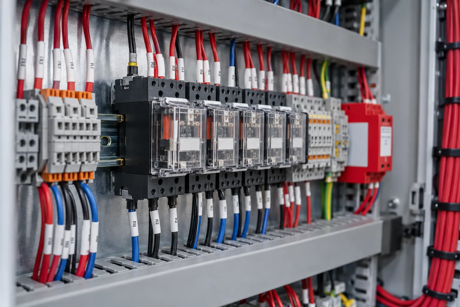
Relays and interfaces in fire systems
How dry contacts, monitored inputs, outputs and isolation affect integration.
Read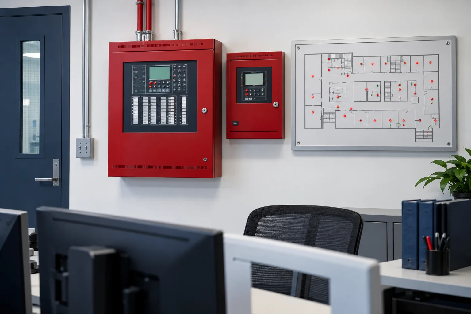
Rehoming, subpanels and mimic panels
Clarify common panel expansion and annunciation terms before modifying a system.
ReadPlan the complete system
Connected Applications And Solutions
Follow the application through equipment selection, interfaces and professional support.
Common Questions
Frequently Asked Questions
Can a fire alarm panel directly control other building equipment?
It can operate approved interfaces, but the required fail-safe state, feedback, circuit monitoring and authority-approved cause-and-effect must be defined.
What makes a notification circuit sufficient?
Calculated and measured sound, visual or speech coverage, compatible approved devices, adequate power and monitored circuit integrity - not simply the number of appliances.
Can the panel software be changed during maintenance?
Only through controlled change management with a current backup, authorisation, documented changes and witnessed regression tests.